The ship-building cranes of the Clyde may be long gone, but the visual memory evoked by these giant structures as they swing round to lift cargo from vessels will live on in a new cable-stayed crossing taking shape in Renfrew.
The twin-leaf swing bridge is the central element of the Clyde Waterfront and Renfrew Riverside project, one of 20 projects in the Glasgow City Region City Deal funded by the Scottish and UK governments with contributions from eight local authorities. It connects Renfrew on the south bank to Clydebank and Yoker on the north bank and it lies approximately midway between the only other river crossings west of Glasgow – the Clyde Tunnel and the Erskine Bridge.
The scheme is led by Renfrewshire Council. Strategic programme manager Norman Yardley explains the importance of having a link at this location: “The bridge carries just two highway lanes, with pedestrian and cycle routes too, and although it allows traffic to cross, it’s really about economic regeneration more than anything.

“We are improving the ability of businesses to interact, for people to access employment, healthcare, education and so on, and to improve both economic and social outcomes for people in the area,” he continues. “We looked at lots of options including a new ferry, which is what was historically here, a tunnel and a bridge.”
Chris Cardno, an associate director at client’s consultant Jacobs, explains how its location and form was established: “Ultimately what dictated its location was connectivity into the local network from a traffic modelling point of view,” he says. “But that did create a number of other constraints such as the navigational width and air traffic requirements – it is on almost the same alignment as the runway at nearby Glasgow Airport.
“It narrowed down the options for movable bridges – bascules or vertical lift bridges were too high when open, and a single span swing bridge would have needed a pier in the water, at a significant cost. Not only that, it would have taken up quite a big proportion of the land,” he says. Ultimately a twin-leaf swing span was the only practical option.
The navigation envelope of the new bridge was set to match that of Erskine Bridge – a 90m clear width and 47m height with the swing spans open – and the deck is low to the water to eliminate the need for long ramps. The deck height improves accessibility from land and the clearance is important so as not to constrain the remaining upstream shipyards and other businesses that use the river, says Yardley.
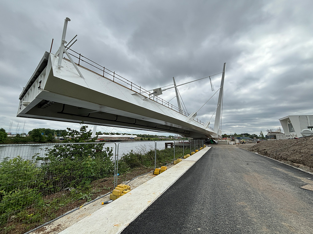
 were used to carry the bridge leaves off the barge and position them over the slew bearings")
“It was important not just to improve the economic environment but also the physical environment,” Yardley he adds. “We wanted something that made a statement.”
The concept design by architect Tony Kettle proposed four masts that are splayed, so that as it opens, the visual interplay between towers and cables conjures an impression of ship-building cranes.
Getting from concept to construction took time and effort, however, with several iterations necessary to achieve a design that maintained the aesthetic vision while also meeting the budget.
The overall project is being delivered by main contractor Graham with steel fabrication by a joint venture of Hollandia and Iemants (part of Eiffage) based in the Netherlands and Belgium respectively. A design team comprising movable bridge designers Hardesty & Hanover and structural engineer Roughan & O’Donovan was appointed by Hollandia at tender phase to develop the concept for construction.
As Cardno explains, the architect’s vision posed some challenges. “The masts were splayed out from the deck but also inclined in the longitudinal plane, which introduced quite significant design inefficiencies and additional fabrication costs. We looked at relaxing some of those aesthetic requirements and removing the skew so the piers are now effectively square.”
According to Hardesty & Hanover principal Jim Phillips, the construction cost of the structure was slashed by £20m – around a fifth – by making the design more efficient. “We actually went through the tender process twice; in the first phase we were held to the same geometry but we did try and make the structure more cost-effective.”
The concept design had seven stays from each mast to the main span, and three to the back span, which created an imbalance at the mast and was more than was necessary to support the deck in any case, says Phillips. This was reduced to three on each span.

The other major adjustment was in the cross-section of the deck. The concept design proposed a full orthotropic box section, Phillips reveals, but this was adapted to a pair of boxes, one along each edge of the deck, reducing the weight of the structure still further and creating a more direct load path to the masts and the central pivot.
But despite these measures, the tender price was still above the client’s budget, making the project unaffordable. In the second round, the council asked the two remaining bidders to propose value engineering measures to try and bring the cost down further.
“That was a real opportunity for us,” says Phillips. “We were able to change the proportions of the spans to reduce the amount of counterweight needed.” Originally each leaf had a 67m main span and 25m back span, which he describes as a ‘very poor proportion’ for this type of bridge. By taking 2m off the main span and adding it to the back span, the amount of steel ballast needed to balance the bridge could be reduced.

“We also took out the skew of the masts, so that the pivot girder, which connects the two masts across the top of the slewing bearing is now at 90o to the axis of the bridge,” he says.
Other measures included reducing the skew at the centre joint from 20° to just 6°, which reduced the transverse imbalance and the potential for excessive force in the nose locks and redesigning the rear of each leaf from a skew to a radius, which is the more conventional solution for this type of structure.
“We worked very hard to try and balance the maximum loads on the 6.7m-diameter slewing bearing,” says Phillips. “It’s got a forward imbalance and we jack it down at the back to minimise the moment that is applied to the bearing. That bearing is the linchpin – if you have to fix it that’s a major operation,” he says. However there is a designed-in method for replacing it, using jacks installed under the bridge deck – these jacks have already been used to set the two bridge decks into position during the installation.

The main structure was not the only part of the contract to go through value engineering by Graham’s team, Cardno recalls. “There was an existing box culvert under the north abutment that had to be diverted. The exemplar was to build another boxed culvert off line; Graham’s team proposed an open ditch channel with discrete crossing points that would facilitate access into future development land. It had the multiple benefits of being environmentally friendly, looking better, and minimising need for significant precast or insitu concrete culvert sections.”
With the cost of the contract finally aligning with the client’s budget – at £117m in total – detailed design started in November 2021 and work on site kicked off in May the following year.
Graham contracts manager Jim Armour explains that the plan was always to build each bridge leaf in a separate yard, sail them to site and install them in a single piece. “It’s a large structure that we wanted to construct in a controlled environment and there are not many yards around that have the facilities to do that. We had previous experience of building a bridge with Hollandia and they suggested teaming up with Iemants.

“Having them both built by the same company would have meant waiting for the first one to be finished before the second one could start – and that would have extended the programme significantly. We can take advantage of two companies that have a wider resource, and it allows them to share the risk too,” Armour adds.
Sheet pile cofferdams each covering 25m2 were built on each side of the river, within which the main pier for each slew bearing was built. Concrete works took around four and a half months to complete, recalls Armour, with each side managed separately to accommodate the fact that it was a half-hour journey between them.
Ground conditions were challenging but not unexpected for the Clyde – particularly on the north side, on the alignment from which the river had migrated over time. “You commonly have a band of made ground but you very quickly get into your river muds, silts, alluvium,” explains Cardno. “Then you go into glacial till – rock is way down.”

The bridge leaves were shipped by barge from Rotterdam by heavy-lift specialist Sarens, a journey that took just seven days. The installation process was impressively smooth, says Phillips, with each structure offloaded directly to its final position.
The total operation took about six hours with approximately two hours of actual lifting and adjustment. The two leaves were installed within a few weeks of one another.
Preparation involved installing temporary works in the river with mooring piles and ramps to each bank. On arrival, the barge was moored parallel to the river bank to allow the bridge leaf to be raised by two sets of self-propelled modular transporters (SPMTs), driven off the barge and positioned over the slew bearing.
The leaf was then lowered by the SPMTs onto the four permanent bridge jacks. These had scope for much finer control on the final positioning, which involved correctly aligning more than 100 threaded rods with openings in the underside of the deck.
The procedure also enabled a final weigh-in for the structure, as Phillips explains: “We checked the bridge weight at several stages during construction, but this process allowed us to determine any final counterweight adjustments.”
The two leaves are currently open to navigation and will come together for the first time in early July, Phillips says. The project is due for completion in October this year.

Got a story? Email news@theconstructionindex.co.uk